
How to Install a Ford Racing Intake Manifold for a 2005-2010 Mustang GT
This Mustang Parts Installation Guide Works For
| Tools Required
Installation Time: 2 Hrs |
Installation
Step 1 (Depressurize the Fuel System)
You need to depressurize the fuel system by disconnecting the Fuel Pump Driver Module (FPDM). This can be found in the spare wheel well in the trunk.

After the Module has been disconnected start the car and run until it stalls and then crank the engine for an additional 10 seconds. Note your car may or may not start.
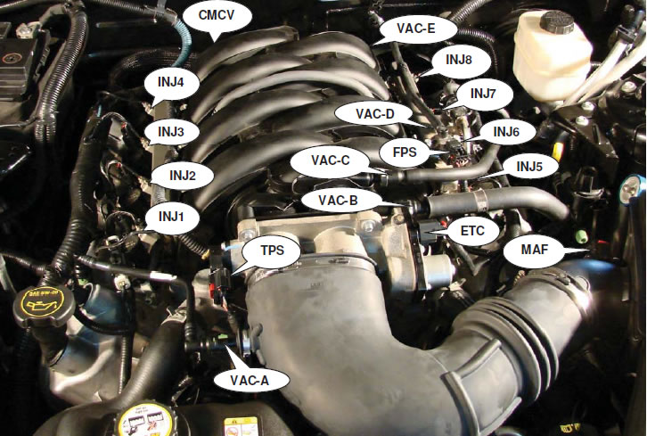
Step 2 (Disconnect Electrical & Vacuum Connections Remove Intake)
Disconnect the following electrical and vacuum connections found in the engine bay:
A. Negative Terminal on the Battery (8mm Socket)
B. Throttle Position Sensor (TPS)
C. Mass Air Flow Sensor (MAF
D. Electric Throttle Connection (ETC)
E: CMCV (Charge Motion Control Valves) -- Located behind the Manifold the CMCV connector has a push-in retainer that needs to be removed from the bracket with a panel-popper tool. This connection does not get used with the new intake manifold.
F. FPS (Fuel Pressure Sensor)
G. Fuel Injector Connections (4 on each side of the Intake Manifold)
H. Vacuum A - E
I. Remove your intake box or filter. If you have the stock intake use a flathead screwdriver to loosen the connections.
NOT ALL ARE PICTURED BELOW!!!!

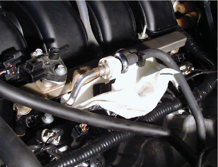
Step 3: (Disconnect Fuel Line and Remove Fuel Rails)
Use a 5/8" Fuel Line Quick Disconnect tool and disconnect the fuel line. Place rags or towels under the connection as there will still be fuel in the lines and it will leak. Also wear goggles in case there is still some pressure within the fuel lines.
Remove the two bolts holding the fuel rails using an 8mm Deep Socket. After the bolts have been removed remove the fuel rail with fuel injectors still connected
Step 4: (Remove the Throttle Body)
Remove the throttle body from the Intake Manifold using an 8mm socket for the top two bolts and a 10mm socket for the bottom two bolts.
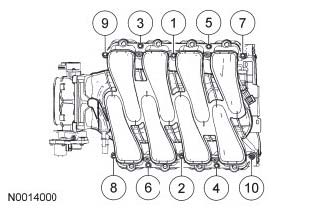
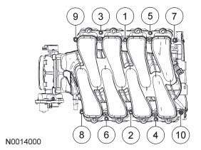
Step 5 (Unbolt and remove the Intake Manifold)
Unbolt the Intake Manifold using a 10mm deep socket. There are 10 bolts holding the manifold in place and they need to be removed in correct sequence. Follow the sequence below.
4 | 1 |
| 6 | 7 |
| 10 | 9 |
| 8 | 5 |
| 2 | 3 |
After all bolts have been removed remove the Intake Manifold and set aside.
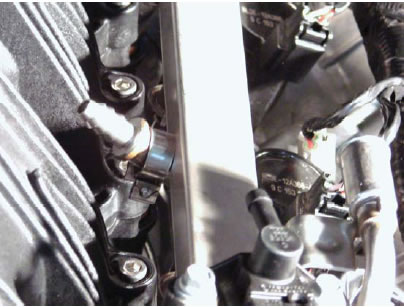
Step 6: (Modify the Alternator Bracket)
Remove the Alternator Bracket using an 8mm and 10mm socket.
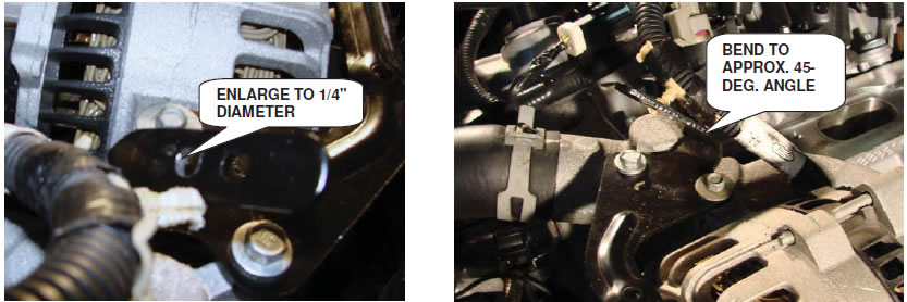
After Removing Bracket. Enlarge the bottom hole using 1/4" drill bit. After enlarging the hole reattach the bracket and torque to 89lb per inch. You will need to bend the tab forward about 45 degrees to allow clearance for alternator wire.
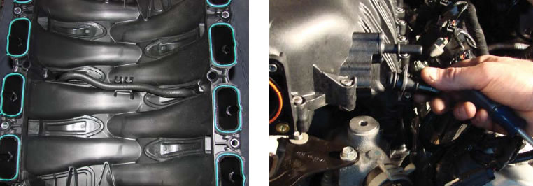
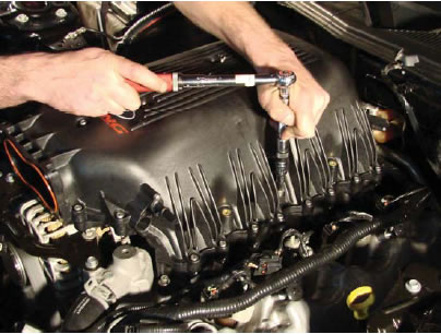
Step 7 (Install Intake Manifold)
Route the supplied fuel line crossover on the underside of the manifold. Install the manifold and hand tighten with new supplied bolts. The new bolts will require a
5mm Hex Key and will need to be tightened to 89lb per inch following the sequence below.
| 7 | 10 |
| 5 | 4 |
| 1 | 2 |
| 3 | 6 |
| 9 | 8 |
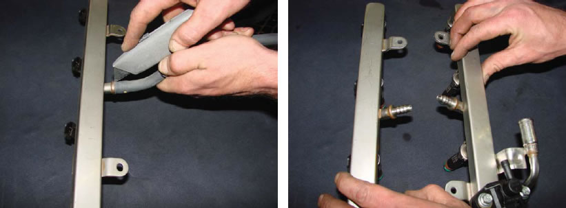
Step 8 (Modify and Reattach Fuel Rail)
Cut the fuel line crossover from the fuel rail using a razor and discard.
Reconnect fuel rails by pushing gently on fuel injectors to ensure they are seated. Attach new crossover line to fuel rail an d used the supplied clamps. The clamps can be tightened with a flathead screwdriver
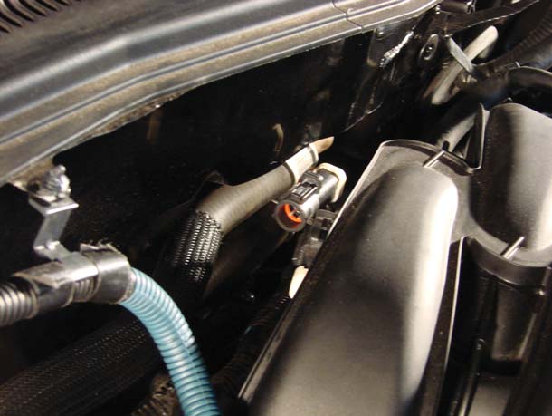
Step 9 (Shorten Vacuum Tube)
The vacuum tube connecting the intake manifold to the valve cover on the driver's side will need to be shortened by 1.5". Start by cutting the insulating cover and by 1.5" but do not cut through to the plastic tube. Peel back cover.
Measure 1.5" from the beginning of the tube but not from the connector and cut tube. Remove the connector and reattach by heating the end of the tube with a heat gun or hairdryer. The tube will shrink around the connector as it cools.
Step 10 (Reattach all electrical and vacuum connections) Reattach :
A. Throttle Position Sensor (TPS)
B. Mass Air Flow Sensor (MAF)
C. Electric Throttle Connection (ETC)
D. FPS (Fuel Pressure Sensor)
E. Fuel Injector Connections (4 on each side of the Intake Manifold)
F. Vacuum A - E
G. Air Filter
H. Negative Terminal on the Battery (8mm Socket)
I. FPDM
Start the car and check for leaks. Load new tune. DO NOT DRIVE UNTIL YOU HAVE A TUNE!
Continue Shopping
- Shop all Ford Racing Performance Parts
- Shop all 05-09 Mustang Intake Manifolds and Plenums
- Shop all 05-09 Mustang Engine Parts
Dylan I.
Nathaniel F.
Charles M
William L
Benjamin T
Johann S
Warren M
Ronald M
Jim G
Kristen H
Michael N
Jaime C
Alex G
Stacey H
Richard S
Josh W
Ricky I
Phillipe D
Greg W
Erin O
Dustin P
Heather W
Deborah L
Anthony A
Kenny O
Chris G
Bruce C
Kelvin A
Ronald H
Brian T
Anthony E
Daniel B
Ricky I
Linda W
Michael M
Emir H
Doug B
Chris G
Louis D
William S
Stefan O
Johnny B
James J
Noah B
Mac S
Richard M
Dennis S
Noah B
Richard M
Eric J
Michael A
Spencer T
Robert R
Sara A
William B
Erik S
James R
Kary K
John N
Emir H
Jonathan B
Sherry C
Josh W
William N.
Stratis R
Leo S
Joseph W
James C
George Y
Stephen C
David L
Richard A
Charles M
Albert B
Kyle P
Jim W
Walt S
Ronald B
Stephen H
Carlos G
Paul C
Aaron W
Robert S
Valerie J
Richard A
Ernesto C
Robert R
Steven T
Greg M
Jordan C
Ryan D.Customer Support
I grew up a Chevy kid, but when it came time to get a muscle car of my own, I fell in love with Mustangs. Been bleeding blue ever since. Being a Customer Service Rep at American Muscle lets me talk about the cars I love and how to make...
DaveTraining Director
I have been toying with Mustangs since before a driver's license was even an option. I've owned somewhere around 15 and I'm not done by a long shot. It all started with a 175 HP pearl white convertible Fox Body. It sparked my love for Mustang's and that sparked a...
BillCustomer Support
I'm currently a student at Penn State University studying political science. I've run a performance shop on the side for over a year now, and I've been working on cars for 7 years now. I've done transmissions, engines, and suspensions on many different cars. I used to be a Chevy...
GerryCustomer Support
When I retired after working for the city of Philadelphia and Septa I decided it was time to relive my earlier years and buy a real muscle car. (I also took on this job at AmericanMuscle for fun - I love the car and the community and belong to several...
KarenCustomer Support
I am a Mustangaholic. Do not try to cure me, I am perfectly OK with being one. I have owned over 10 Mustangs in my lifetime already. I currently have just 5 (I did own 8 at one time). I fell in love for the first time when I was...
DuncanMarketing
Got into cars when I was young. Always was into the Mustangs because of the movie 'Gone in 60 Seconds' with the 1967 Shelby GT500 Fast back when I was growing up. I am currently attending Universal Technical Institute for Automotive/Diesel and Ford Fact program. I just started working at...
DannBama Tuning Specialist
I may be the only person to ever brave a winter with drag radials on a Mustang, while still daily driving it. Dont worry, I finally got them off in the spring (day late and a dollar short, right?), and I promptly finished those tires at our company picnic in...
CraigProduct Development
I have always been around Mustangs in my professional life, either fixing them as a mechanic, selling them at dealerships, or modding them here at AmericanMuscle. Instead of starting right away with the power mods, I started looking more into suspension and weight reduction. I have always dreamed of entering...
LeeCustomer Support
I am a diehard Mustang fanatic. I first fell in love with Mustangs when I was 15 years old and I found a 1966 Mustang coupe restoration project. That was the beginning of my addiction. I quickly added a 1993 Mustang LX 5.0 to my collection which served as my...
JamieCustomer Support
This whole story starts when I was 15 and I had to have a foxbody. So I went out and found the loudest fastest foxbody that 5 grand could buy. When I realized that this thing was a certain death trap I sold it and moved onto the 2000 GT...
HeatherCustomer Support - Lead
I went to automotive school in Exton, PA, and worked as a mechanic for a while. My dad is a huge Ford guy; he used to drag race and my uncles raced motorcycles so I was always in the garage growing up. Working here is nice because it's not as...
Ryan MBama Tuning Specialist
I got my first Mustang when I was 16, a two tone 91 GT red and silver with a sunroof that didnt leak! And needless to say I was a bit timid to do work on it, I hadnt modified any vehicle before outside of installing a CD player. I...
DrewCustomer Support
Recently I bought my first home, the selling point for the house was not the amount of land, bedrooms, or bathrooms like how most people would choose a home. I made my choice based on the garage where the mustang sleeps. The garage is completely finished with painted floors, walls,...
Mike JCustomer Support - Manager
My first car was a 1989 Ford Mustang Saleen Convertible that I used as my test car to learn about working on Mustangs. Foxbodies have become my passion and now I pretty much consider myself a Foxbody expert. My dream project car is a Foxbody with a 03-04 cobra swap...
KarenCustomer Support
I am a Mustangaholic. Do not try cure me, I am perfectly ok with being one. I have owned over 10 Mustangs in my lifetime already. I currently have just 5 (I did own 8 at one time). I fell in love for the first time when I was 13....
BrickPurchasing
I was a customer first - 7 years ago I came in to buy parts, got in an argument with someone about a part, and won. I left with my parts and a new job and I've been here ever since. I knew when I came to work at AmericanMuscle,...
JeffMarketing
I've loved Mustangs for as long as I can remember. My dad was a Camaro guy growing up, but his first work truck was a Ford, and we've been a Ford-only family ever since. My dad is a sheet metal worker/mechanic, so everything I know about my car I learned...
DanCustomer Support
All my other cars were all-wheel drive, my brother had an 04 cobra and i wanted to compete and beat him with naturally aspirated so i went with a mach1 - and beat him. Now he works here too! I got lucky and was able to find one of the...
SandyOperations
I have only driven 2 manual transmission Mustangs, the 1st was the car that taught me how to drive stick shift. The other is my current daily driver. A very memorable moment about my GT500 happened when I purchased a JLT CAI and SCT tuner. I thought the car was...
KarenCustomer Support
I am a Mustangaholic. Do not try cure me, I am perfectly ok with being one. I have owned over 10 Mustangs in my lifetime already. I currently have just 5 (I did own 8 at one time). I fell in love for the first time when I was 13....
Chris RMarketing
I was raised by a car family. Drag racing and the Ford blue oval were always a huge part of our household. During my high school years, working on cars and participa....err watching street races probably helped further pull my focus from my priorities and I was hooked. After high-school...
LeeCustomer Support
I am a diehard Mustang fanatic. I first fell in love with Mustangs when I was 15 and I found a 1966 Mustang coupe restoration project. That was the beginning of my addiction. When it came time for my wife to get a new car, she had already driven my...
MikeLead Calibrator & Ford Performance Expert
Ive had 18 Mustangs, ranging from a stock 66 coupe to a low 9-second Fun Ford Weekend Street Renegade 96 GT that made 888 RWHP. (308 cid motor, Edelbrock heads, intake and topped off with a Paxton Novi 2000R supercharger pushing 30 psi of boost). My best pass in that...
BrianContent Development
Mustangs hold a special place in my heart. My father owned a 65 mustang when he was younger, but a friend wrecked it. The grille pony still sits on his workbench. Until getting my own pony, I had no clue why he would keep a metal horse for so long....
JamieCustomer Support
This whole story starts when I was 15 and I had to have a foxbody. So I went out and found the loudest fastest foxbody that 5 grand could buy. When I realized that this thing was a certain death trap I sold it and moved onto the 2000 GT...
GerryCustomer Support
When I retired after working for the city of Philadelphia and Septa I decided it was time to relive my earlier years and buy a real muscle car. (I also took on this job at AmericanMuscle for fun - I love the car and the community and belong to several...
EthanInventory Control
I've worked here for 3 years now and done pretty much everything in the warehouse from mounting and balancing wheels/tires, driving the forklift, shipping, and receiving. Both my brothers worked here in other departments, keeping it in the family! My car philosophy's pretty simple, I just want to get where...
EXPLORE
CUSTOMER SERVICE
 |
 |
 |
 |
 |
 |