
How to install a K&N FIPK Cold Air Intake on your 2007-2009 GT Mustang
This Mustang Parts Installation Guide Works For
| Tools Required
Installation Time: (approx) 1 Hour |
Installation
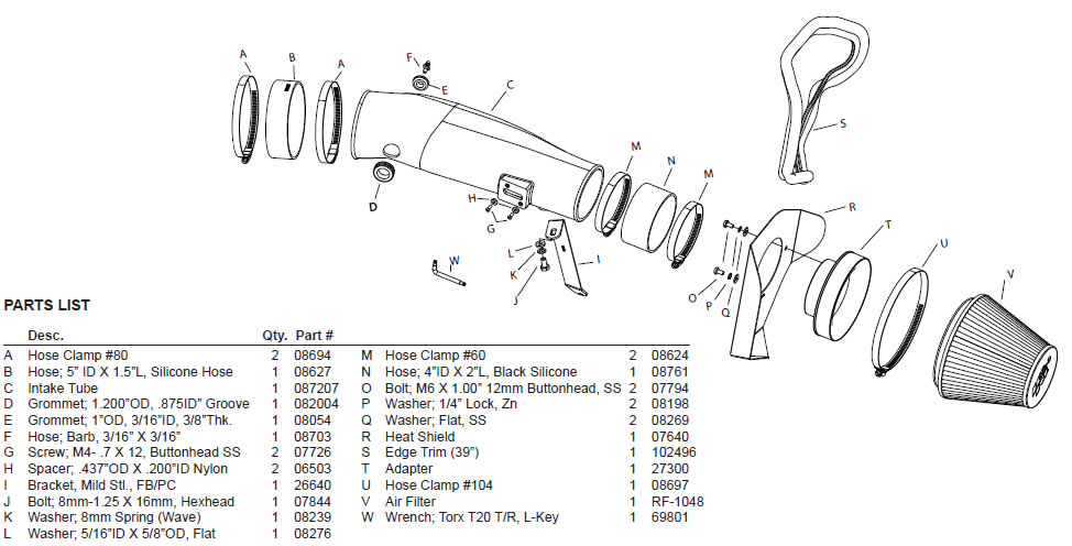
PARTS LIST:
| Desc | Qty. | Part # | |
|---|---|---|---|
| A | hose clamp #80 | 2 | 08694 |
| B | hose; 5 id x 1.5l, silicone hose | 1 | 08627 |
| C | intake tube | 1 | 087207 |
| D | grommet; 1.200od, .875id groove | 1 | 082004 |
| E | grommet; 1od, 3/16id, 3/8thk | 1 | 08054 |
| F | hose; barb, 3/16 x 3/16 | 1 | 08703 |
| G | screw; m4- .7 x 12, button head ss | 2 | 07726 |
| H | spacer; .437od x .200id nylon | 2 | 06503 |
| I | bracket; lgl, 57-2571, mild stl, fb/pc | 1 | 26640 |
| J | bolt; 8mm-1.25 x 16mm, hexhead | 1 | 07844 |
| K | washer; 8mm spring (wave) | 1 | 08239 |
| L | washer; 5/16id x 5/8od, fl at | 1 | 08276 |
| M | hose clamp #60 | 2 | 08624 |
| N | hose; 4id x 2l, black silicone | 1 | 08761 |
| O | bolt; m6 x 1.00 12mm buttonhead, ss | 2 | 07794 |
| P | washer; 1/4 lock, zn | 2 | 08198 |
| Q | washer; fl at, ss | 2 | 08269 |
| R | heat shield | 1 | 07640 |
| S | edge trim (39) | 1 | 102496 |
| T | adapter; 454 | 1 | 27300 |
| U | hose clamp #104 | 1 | 08697 |
| V | air fi lter | 1 | RF-1048 |
| W | wrench; torx t20 t/r, l-key | 1 | 69801 |
NOTE: FAILURE TO FOLLOW INSTALLATION INSTRUCTIONS AND NOT USING THE PROVIDED HARDWARE MAY DAMAGE THE INTAKE TUBE, THROTTLE BODY AND ENGINE.
TO START:
- Turn off the ignition and disconnect the negative battery.
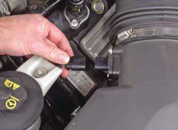
- Depress the locking tab and then unhook the mass air sensor electrical connection.
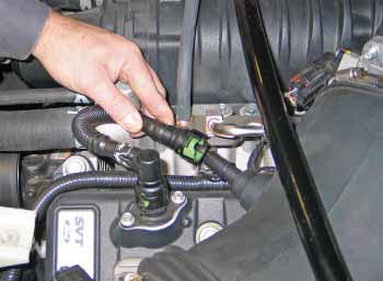
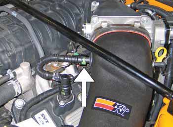
- Rotate the green locking tab and then disconnect the crank case vent hose from the intake tube.
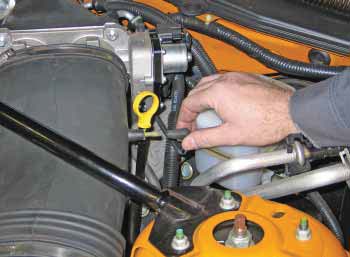
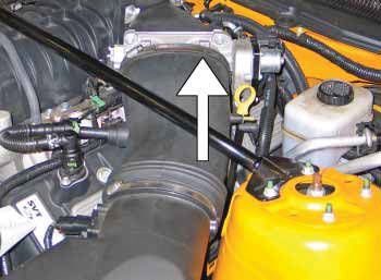
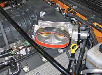
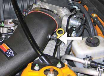
- Disconnect the vacuum vent line as shown.
- Loosen the intake hose clamp at throttle body.
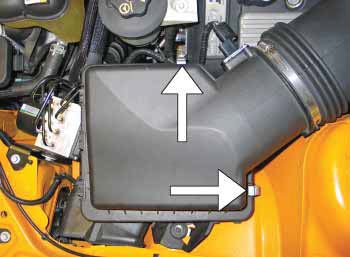
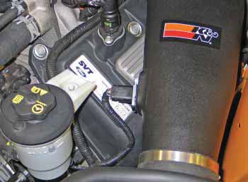
- Unlatch the two upper air box retaining clips shown.
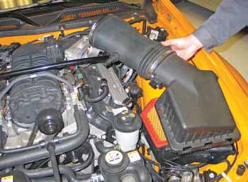
- Remove the intake tube and air box lid from the vehicle.
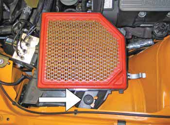
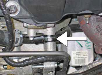
- Remove the lower air box retaining bolt shown.
- Remove lower air box housing from the vehicle.
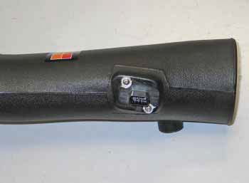
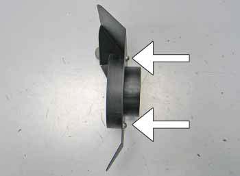
- Using the T20 torx wrench provided, remove the mass air sensor retaining screws and remove the mass air sensor as shown.
- Install the mass air sensor into the K&N intake tube and secure with the provided spacers and m4 bolts.
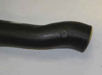
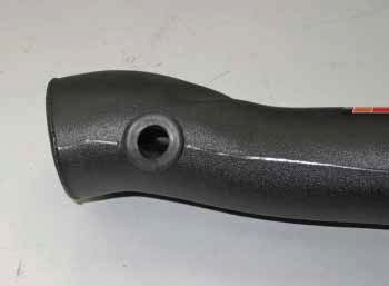
- Install the supplied ¼id vent grommet into the K&N intake tube as shown.
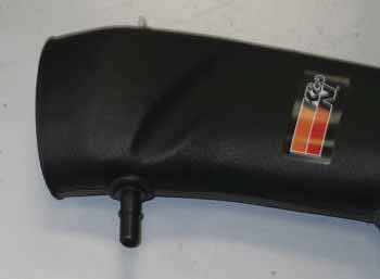
- Install the supplied ¼ hose mender into the grommet installed in step #12.
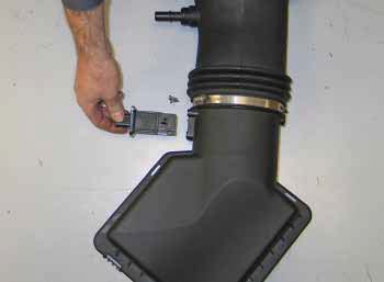
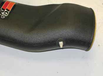
- Install the supplied crank case vent grommet into the K&N intake tube as shown.
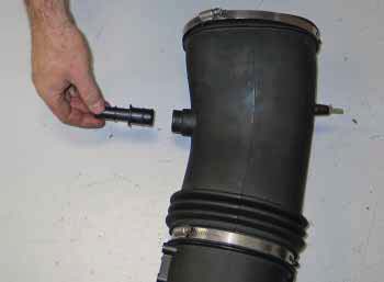
- Cut the clamp securing the Crank case vent fi tting into the factory intake tube and then remove the fi tting from the intake tube as shown.
- Install the factory crank case vent fi tting into the grommet installed into the K&N tube in step #14.
- Install the supplied silicone hose (08627) onto the throttle body and secure with the provided hose clamp.
- Remove the upper alternator mounting bolt shown
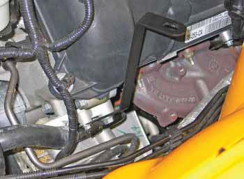
- Install the tube mounting bracket (08761) onto the alternator bracket with factory bolt removed in step #18.
- Install the K&N intake tube into throttle body and align with mounting bracket, then secure with the provided hose clamp and hardware.
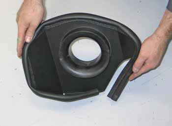
- Install the fi lter adapter onto the heat shield using the provided hardware
- Install the edge trim onto the heat shield assembly as shown.
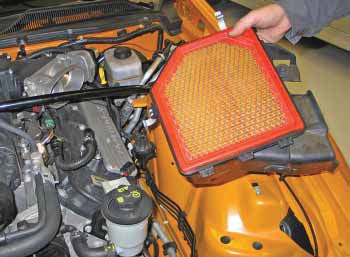
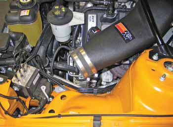
- Install the silicone hose (08698) onto the intake tube and slide it past the bead on the end of the tube for clearance while installing the fi lter assembly.
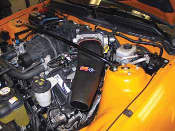
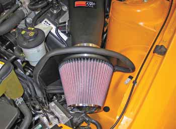
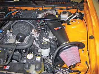
- Set the fi lter assembly into the position and slide the silicone hose into position and secure it to the fi lter assembly and intake tube with the provided hose clamps.
- Connect vacuum vent line onto the ¼ hose mender installed into the K&N intake tube during step #13.
- Connect the crank case vent hose onto the factory fi tting installed into the K&N intake tube in step #15.
- Reconnect the mass air sensor electrical connection.
- Reconnect the vehicles negative battery cable. Double check to make sure everything is tight and properly positioned before starting the vehicle.
- The C.A.R.B. exemption sticker, (attached), must be visible under the hood so that an emissions inspector can see it when the vehicle is required to be tested for emissions. California requires testing every two years, other states may vary.
- It will be necessary for all FIPKs to be checked periodically for realignment, clearance and tightening of all connections. Failure to follow the above instructions or proper maintenance may void warranty.
NOTE: K&N recommends that customers do not discard factory air intake.
ROAD TESTING:
- Start the engine with the transmission in neutral or park, and the parking brake engaged. Listen for air leaks or odd noises. For air leaks secure hoses and connections. For odd noises, fi nd cause and repair before proceeding. This kit will function identically to the factory system except for being louder and much more responsive.
- Test drive the vehicle. Listen for odd noises or rattles and fi x as necessary.
- If road test is fi ne, you can now enjoy the added power and performance from your kit.
- K&N suggests checking the Filtercharger element periodically for excessive dirt buildup. When the element becomes covered in dirt (or once a year), service it according to the instructions on the Recharger service kit, part number 99-5050 or 99-5000.
Continue Shopping
- Shop all K&N Engineering Mustang Parts
- Shop all 05-09 Mustang Cold Air Intakes
- Shop all 05-09 Mustang Engine Parts
Dylan I.
Nathaniel F.
Charles M
William L
Benjamin T
Johann S
Warren M
Ronald M
Jim G
Kristen H
Michael N
Jaime C
Alex G
Stacey H
Richard S
Josh W
Ricky I
Phillipe D
Greg W
Erin O
Dustin P
Heather W
Deborah L
Anthony A
Kenny O
Chris G
Bruce C
Kelvin A
Ronald H
Brian T
Anthony E
Daniel B
Ricky I
Linda W
Michael M
Emir H
Doug B
Chris G
Louis D
William S
Stefan O
Johnny B
James J
Noah B
Mac S
Richard M
Dennis S
Noah B
Richard M
Eric J
Michael A
Spencer T
Robert R
Sara A
William B
Erik S
James R
Kary K
John N
Emir H
Jonathan B
Sherry C
Josh W
William N.
Stratis R
Leo S
Joseph W
James C
George Y
Stephen C
David L
Richard A
Charles M
Albert B
Kyle P
Jim W
Walt S
Ronald B
Stephen H
Carlos G
Paul C
Aaron W
Robert S
Valerie J
Richard A
Ernesto C
Robert R
Steven T
Greg M
Jordan C
Ryan D.Customer Support
I grew up a Chevy kid, but when it came time to get a muscle car of my own, I fell in love with Mustangs. Been bleeding blue ever since. Being a Customer Service Rep at American Muscle lets me talk about the cars I love and how to make...
DaveTraining Director
I have been toying with Mustangs since before a driver's license was even an option. I've owned somewhere around 15 and I'm not done by a long shot. It all started with a 175 HP pearl white convertible Fox Body. It sparked my love for Mustang's and that sparked a...
BillCustomer Support
I'm currently a student at Penn State University studying political science. I've run a performance shop on the side for over a year now, and I've been working on cars for 7 years now. I've done transmissions, engines, and suspensions on many different cars. I used to be a Chevy...
GerryCustomer Support
When I retired after working for the city of Philadelphia and Septa I decided it was time to relive my earlier years and buy a real muscle car. (I also took on this job at AmericanMuscle for fun - I love the car and the community and belong to several...
KarenCustomer Support
I am a Mustangaholic. Do not try to cure me, I am perfectly OK with being one. I have owned over 10 Mustangs in my lifetime already. I currently have just 5 (I did own 8 at one time). I fell in love for the first time when I was...
DuncanMarketing
Got into cars when I was young. Always was into the Mustangs because of the movie 'Gone in 60 Seconds' with the 1967 Shelby GT500 Fast back when I was growing up. I am currently attending Universal Technical Institute for Automotive/Diesel and Ford Fact program. I just started working at...
DannBama Tuning Specialist
I may be the only person to ever brave a winter with drag radials on a Mustang, while still daily driving it. Dont worry, I finally got them off in the spring (day late and a dollar short, right?), and I promptly finished those tires at our company picnic in...
CraigProduct Development
I have always been around Mustangs in my professional life, either fixing them as a mechanic, selling them at dealerships, or modding them here at AmericanMuscle. Instead of starting right away with the power mods, I started looking more into suspension and weight reduction. I have always dreamed of entering...
LeeCustomer Support
I am a diehard Mustang fanatic. I first fell in love with Mustangs when I was 15 years old and I found a 1966 Mustang coupe restoration project. That was the beginning of my addiction. I quickly added a 1993 Mustang LX 5.0 to my collection which served as my...
JamieCustomer Support
This whole story starts when I was 15 and I had to have a foxbody. So I went out and found the loudest fastest foxbody that 5 grand could buy. When I realized that this thing was a certain death trap I sold it and moved onto the 2000 GT...
HeatherCustomer Support - Lead
I went to automotive school in Exton, PA, and worked as a mechanic for a while. My dad is a huge Ford guy; he used to drag race and my uncles raced motorcycles so I was always in the garage growing up. Working here is nice because it's not as...
Ryan MBama Tuning Specialist
I got my first Mustang when I was 16, a two tone 91 GT red and silver with a sunroof that didnt leak! And needless to say I was a bit timid to do work on it, I hadnt modified any vehicle before outside of installing a CD player. I...
DrewCustomer Support
Recently I bought my first home, the selling point for the house was not the amount of land, bedrooms, or bathrooms like how most people would choose a home. I made my choice based on the garage where the mustang sleeps. The garage is completely finished with painted floors, walls,...
Mike JCustomer Support - Manager
My first car was a 1989 Ford Mustang Saleen Convertible that I used as my test car to learn about working on Mustangs. Foxbodies have become my passion and now I pretty much consider myself a Foxbody expert. My dream project car is a Foxbody with a 03-04 cobra swap...
KarenCustomer Support
I am a Mustangaholic. Do not try cure me, I am perfectly ok with being one. I have owned over 10 Mustangs in my lifetime already. I currently have just 5 (I did own 8 at one time). I fell in love for the first time when I was 13....
BrickPurchasing
I was a customer first - 7 years ago I came in to buy parts, got in an argument with someone about a part, and won. I left with my parts and a new job and I've been here ever since. I knew when I came to work at AmericanMuscle,...
JeffMarketing
I've loved Mustangs for as long as I can remember. My dad was a Camaro guy growing up, but his first work truck was a Ford, and we've been a Ford-only family ever since. My dad is a sheet metal worker/mechanic, so everything I know about my car I learned...
DanCustomer Support
All my other cars were all-wheel drive, my brother had an 04 cobra and i wanted to compete and beat him with naturally aspirated so i went with a mach1 - and beat him. Now he works here too! I got lucky and was able to find one of the...
SandyOperations
I have only driven 2 manual transmission Mustangs, the 1st was the car that taught me how to drive stick shift. The other is my current daily driver. A very memorable moment about my GT500 happened when I purchased a JLT CAI and SCT tuner. I thought the car was...
KarenCustomer Support
I am a Mustangaholic. Do not try cure me, I am perfectly ok with being one. I have owned over 10 Mustangs in my lifetime already. I currently have just 5 (I did own 8 at one time). I fell in love for the first time when I was 13....
Chris RMarketing
I was raised by a car family. Drag racing and the Ford blue oval were always a huge part of our household. During my high school years, working on cars and participa....err watching street races probably helped further pull my focus from my priorities and I was hooked. After high-school...
LeeCustomer Support
I am a diehard Mustang fanatic. I first fell in love with Mustangs when I was 15 and I found a 1966 Mustang coupe restoration project. That was the beginning of my addiction. When it came time for my wife to get a new car, she had already driven my...
MikeLead Calibrator & Ford Performance Expert
Ive had 18 Mustangs, ranging from a stock 66 coupe to a low 9-second Fun Ford Weekend Street Renegade 96 GT that made 888 RWHP. (308 cid motor, Edelbrock heads, intake and topped off with a Paxton Novi 2000R supercharger pushing 30 psi of boost). My best pass in that...
BrianContent Development
Mustangs hold a special place in my heart. My father owned a 65 mustang when he was younger, but a friend wrecked it. The grille pony still sits on his workbench. Until getting my own pony, I had no clue why he would keep a metal horse for so long....
JamieCustomer Support
This whole story starts when I was 15 and I had to have a foxbody. So I went out and found the loudest fastest foxbody that 5 grand could buy. When I realized that this thing was a certain death trap I sold it and moved onto the 2000 GT...
GerryCustomer Support
When I retired after working for the city of Philadelphia and Septa I decided it was time to relive my earlier years and buy a real muscle car. (I also took on this job at AmericanMuscle for fun - I love the car and the community and belong to several...
EthanInventory Control
I've worked here for 3 years now and done pretty much everything in the warehouse from mounting and balancing wheels/tires, driving the forklift, shipping, and receiving. Both my brothers worked here in other departments, keeping it in the family! My car philosophy's pretty simple, I just want to get where...
EXPLORE
CUSTOMER SERVICE
 |
 |
 |
 |
 |
 |