
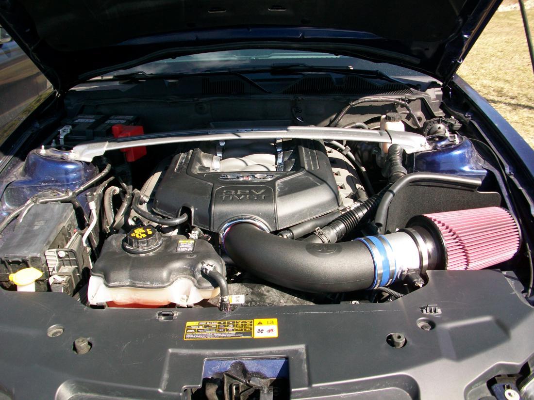
How to Install a C&L Cold Air Intake for 2011-2012 Mustang GT
This Mustang Parts Installation Guide Works For
| Tools Required
Installation Time: 1 Hr |
Installation
Figure 1
- Remove the stock air filter assembly
- Remove strut bar assembly using 13mm deep well socket and wrench for the four nuts holding it to the strut towers and life bar straight off.Fig. 2 (passenger tower nuts removed)
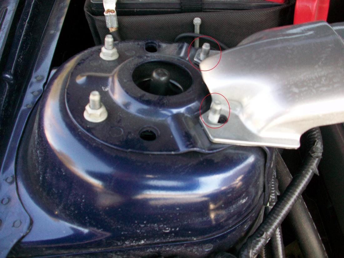
Figure 2
- Remove engine cover by lifting straight up on it by starting with one end (until it releases from the mount) and then moving back to the other end.
- Cover is held down by rubber snaps with two on each side of the engine cover.
Fig. 3 (Cover removed driver’s side)
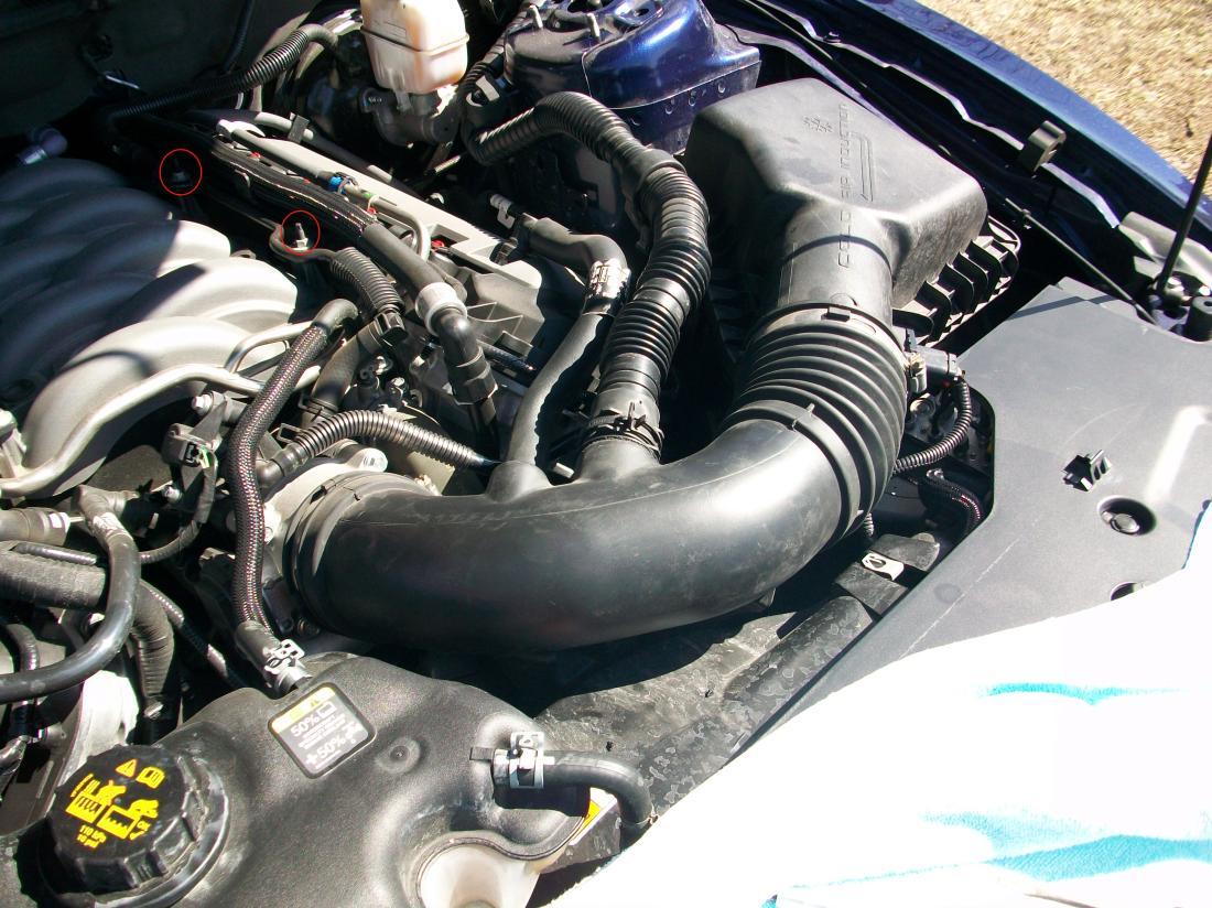
Figure 3
- Loosen the clamp that secures the stock inlet house to the throttle body using a medium flat head screwdriver.Fig.4 (Locations)
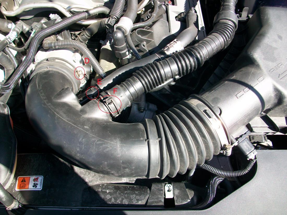
Figure 4
- Disconnect the vacuum house that goes from the valve cover just to the right of the throttle body.
- Push on the small tab holding the fitting in place over the boss of the inlet pipe
- Move this tab over with your thumb and pull connector away towards the driver’s compartment.Fig. 4.e.ii
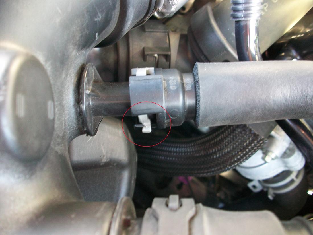
Figure 5
For automatic equipped vehicles there will be a smaller fitting next to the valve cover vent tube.
- Remove from stock intake by pushing down on the yellow tab with your thumb while pulling towards the driver’s compartment.
- Remove the noise transmission tube connector.
- With channel locks or pliers, squeeze the two tabs of the spring loaded clamps together.
- It will lock itself in the ‘open position’.Fig. 4.g.ii
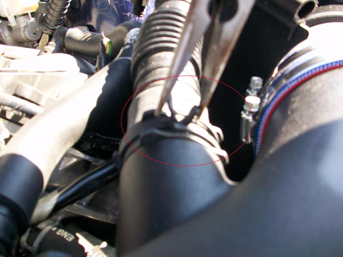
Figure 5
Pull away from the stock intake towards the driver’s compartment and disconnect fastener from the backside of the stock intake box.
Disconnect the MAF sensor located on the front of the air filter housing.
Slide the red tab on the bottom of the connector towards the front of the vehicle.Fig.5
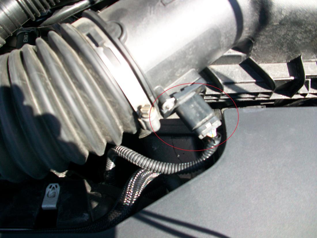
Figure 6
Remove stock air filter housing.- Remove the 10mm bolt from the air filter housing located between the driver’s side fender and air box.Fig. 6
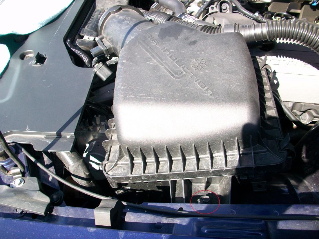
Figure 7
- Pull out any press through nylon fasteners connecting to air filter housing.
- Lift out the entire air filter assembly by lifting slightly upward and to the rear of the vehicle.
- After removal you will be able to see the incoming fresh air feed that enters from between the headlight assembly and the radiator support.Fig. 7
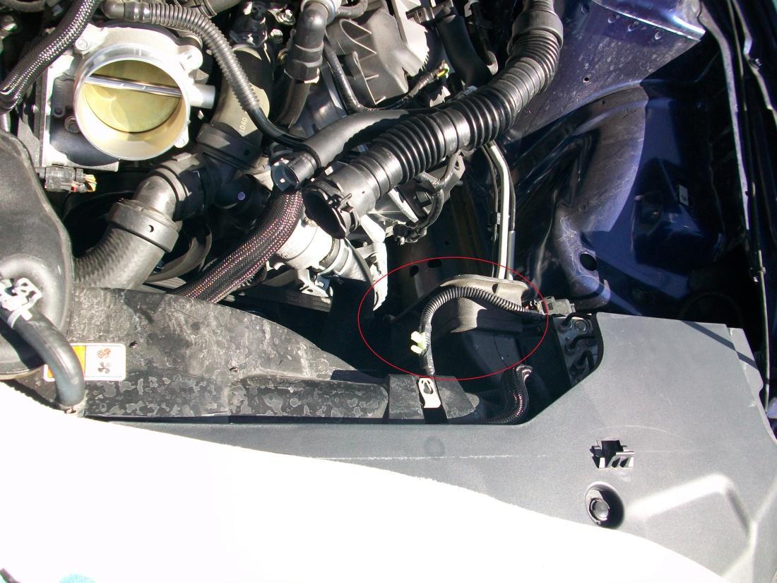
Figure 8
- Remove factory MAF sensor for factory intake assembly
- Using the supplied T-20 torx bit, remove the two screws that secure the factory air meter-sensing element from the stock air box assembly.Fig. 8
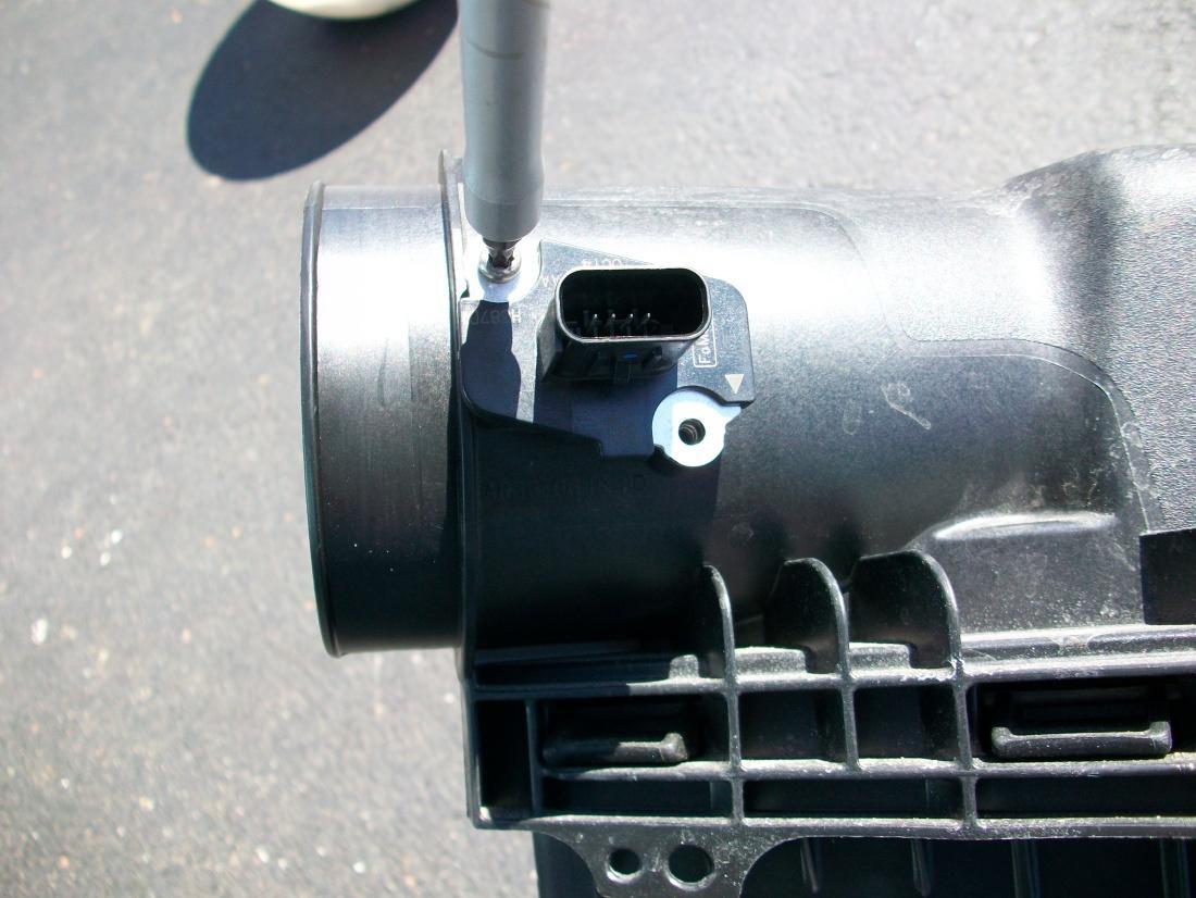
Figure 9
- Make sure the factory rubber seal comes out with the MAF sensor.
2. Install New C&L Intake Assembly
- Carefully lower the sensor in the new aluminum MAF housing from the kit.Fig. 9
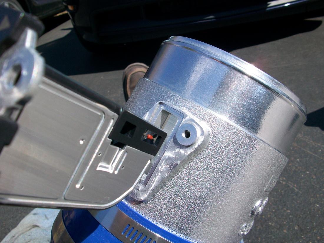
Figure 10
The sensor will only bolt up one way, with the ‘flow’ arrow pointing towards the engine inlet pipe.
Install new filter shroud.
- Lower the new shroud into the engine compartment with the lower ‘scoop’ portion of the shroud going down first, behind and under the rubber seal of the fresh air intake feed.Fig. 10
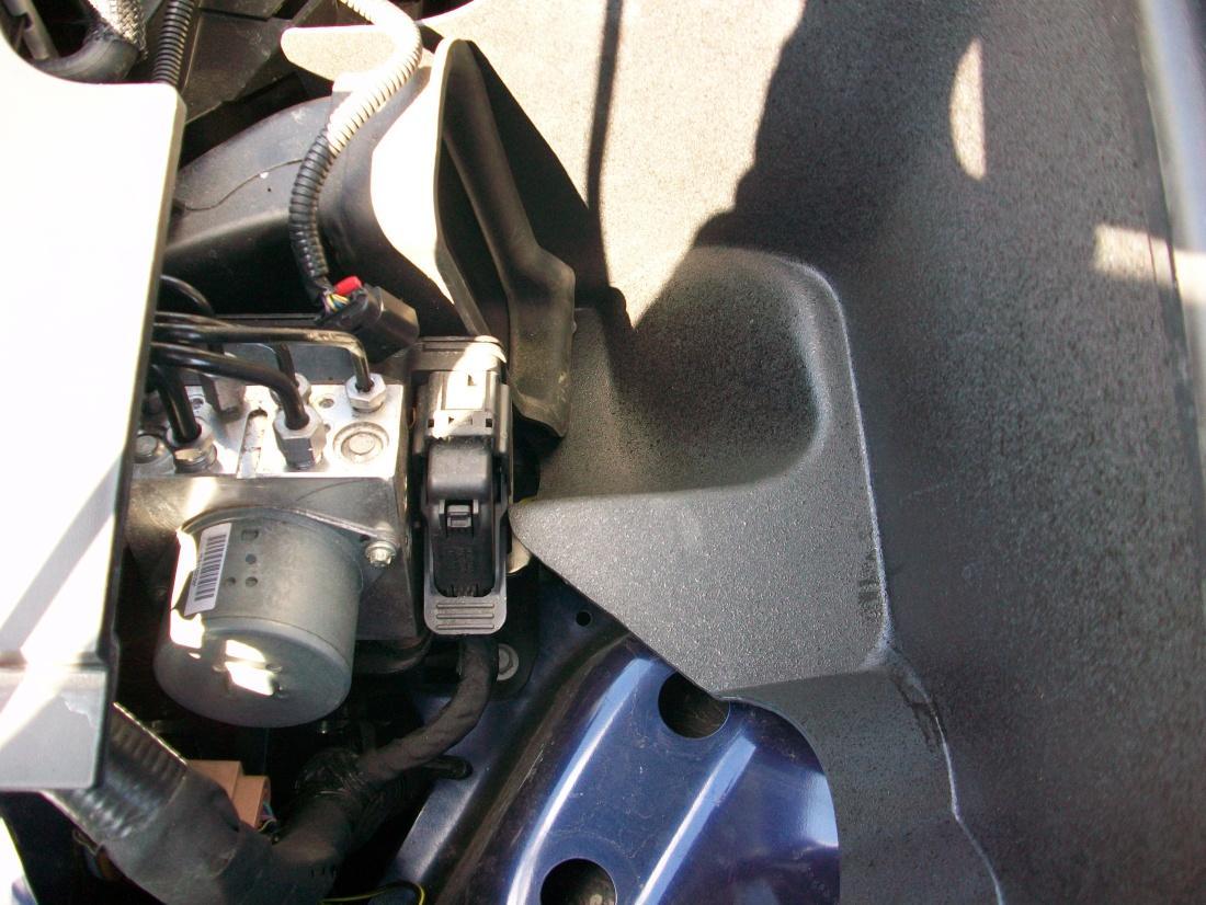
Figure 11
- Move the shroud as far forward as you can under the fresh air feed.
- Locate the 10mm bolt hole from the stock air filter assembly and line up the shroud mounting hole with this hole and reinstall factory 10mm bolt.Fig. 11
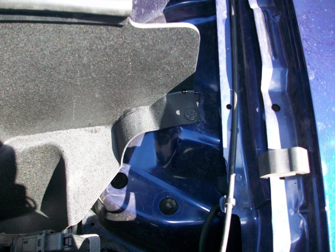
Figure 12
OPTIONAL – Drill a small diameter hole in the bottom of the rubber section of the fresh air feed in a location that lines up with the hole on the bottom of the new shroud and use the kit supplied bolt and nut to mount.
Air Filter Fittings
For Manual transmission – Use the nylon plug and insert and tighten into the hole between the valve cover tube and noise transmission tube.
For Automatic transmission – Use the barbed nipple fitting and insert and tighten into the hole between the valve cover tube and the noise transmission tube.
The fittings are tapered and will self seal by using a wrench.Fig. 12
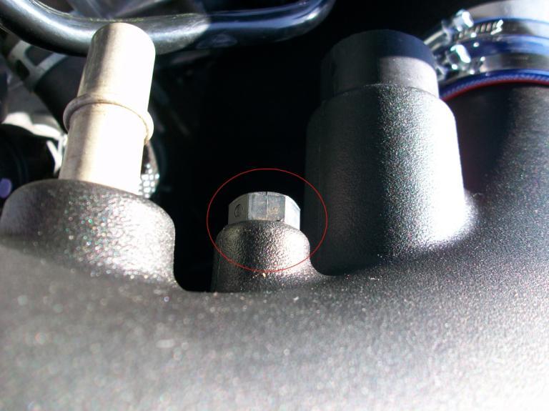
Figure 13
Install the new intake assembly
Lower assembly into the engine compartment and slide the silicone hose over the throttle body and tighten the clamp that goes over the throttle body flange.Fig. 13
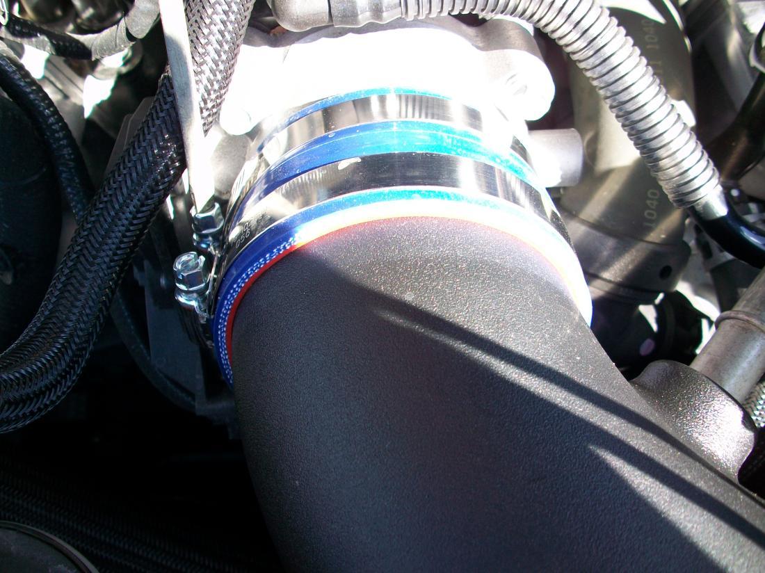
Figure 14
Connect the stock MAF sensor wiring to the MAF sensor mounted on the new air filter assembly.Fig. 14
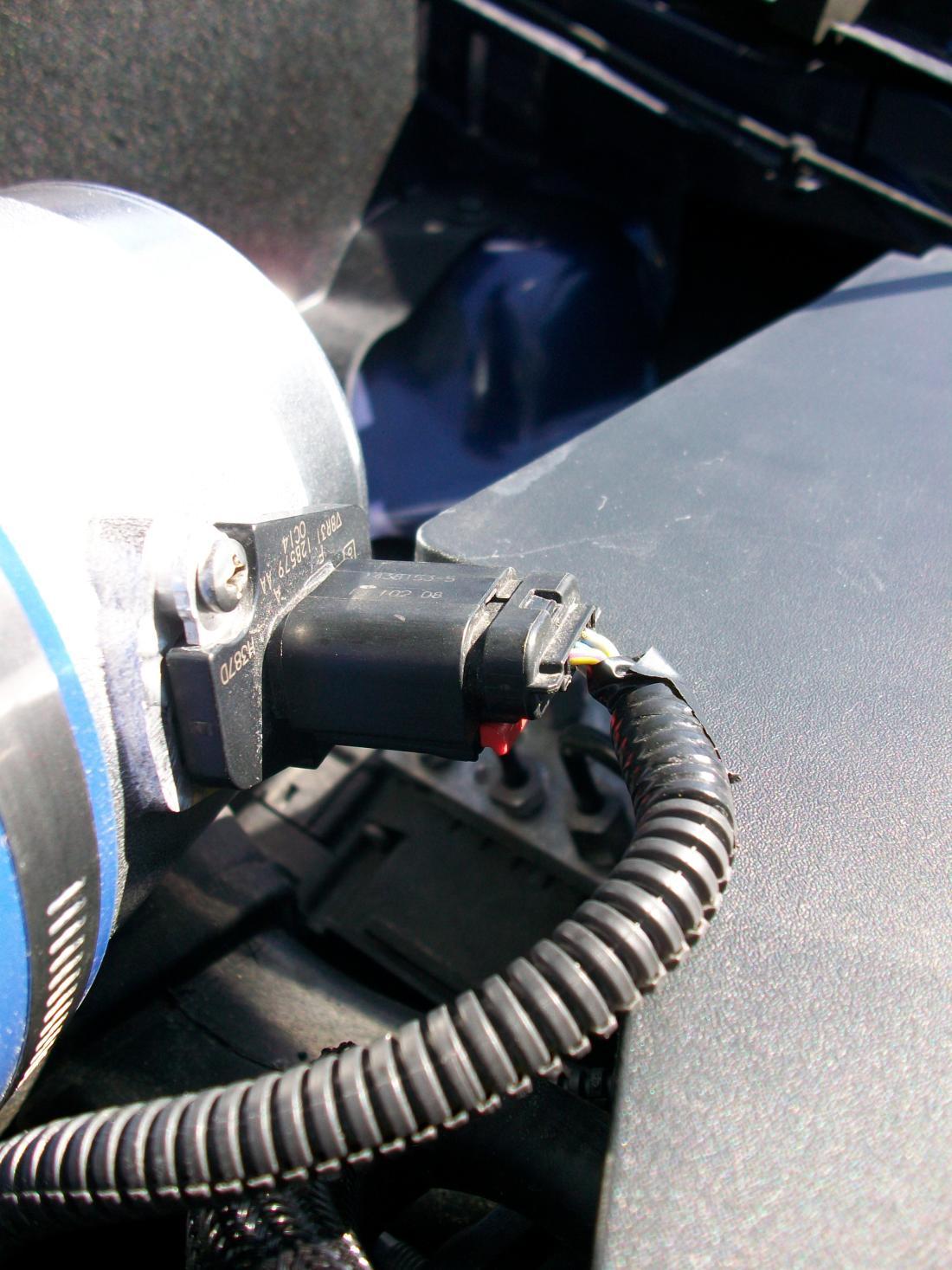
Figure 15
Slide the kit supplied filter over the neck of the new MAF body and orient the clamp so that you can tighten it with a screwdriver.Fig. 15 (Isn’t it massive!)
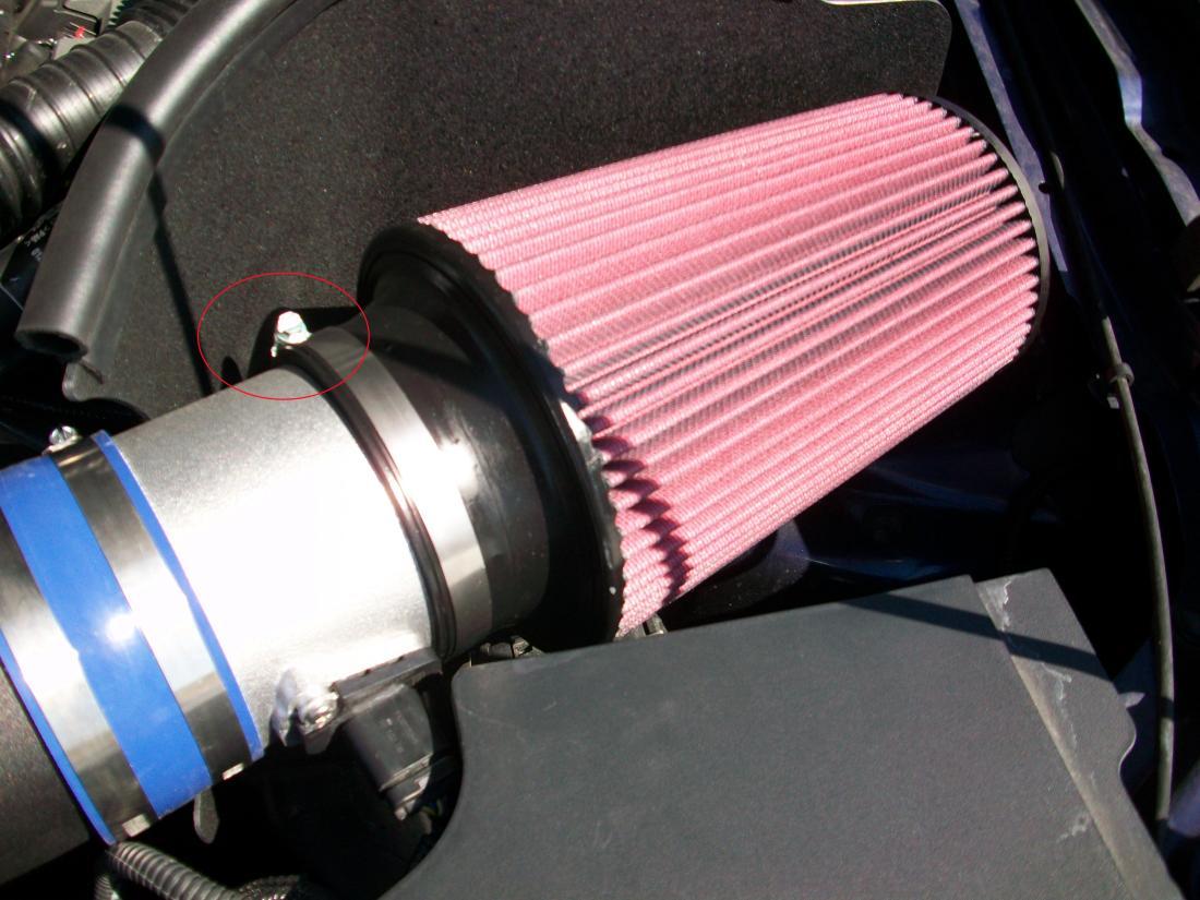
Figure 16
Reconnect the valve cover vent tube fitting to the new inlet tube. It should click into place.
Slide the noise transmission tube all the way over the new mount and release the spring clamp.
TRICK – Take two flat head screwdrivers and release the clamp by applying slight pressure in opposite directions.Fig. 16
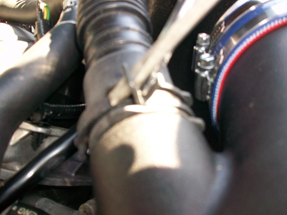
Figure 17
For automatic transmission equipped vehicles reuse the original molded rubber hose to reattached to new fitting.'
- Pull back the plastic conduit and cut the hose just aft of the factory nylon release fitting The exposed 3/8” tubing will then slide over the barded nipple fitting that you previously installed.
- Tighten all clamps once you are satisfied with the alignment of the entire assembly.
- Reinstall the factory engine cover and strut tower brace.
- Lineup the factory engine cover over the rubber mounts and ‘pop’ back on.
- Align strut tower brace over tower studs and mount using the factory 13mm nuts.Fig. 17
Enjoy!
Continue Shopping
- Shop all C&L Mustang Performance Parts
- Shop all 10-13 Mustang Cold Air Intakes
- Shop all 10-13 Mustang Engine Parts
Dylan I.
Nathaniel F.
Charles M
William L
Benjamin T
Johann S
Warren M
Ronald M
Jim G
Kristen H
Michael N
Jaime C
Alex G
Stacey H
Richard S
Josh W
Ricky I
Phillipe D
Greg W
Erin O
Dustin P
Heather W
Deborah L
Anthony A
Kenny O
Chris G
Bruce C
Kelvin A
Ronald H
Brian T
Anthony E
Daniel B
Ricky I
Linda W
Michael M
Emir H
Doug B
Chris G
Louis D
William S
Stefan O
Johnny B
James J
Noah B
Mac S
Richard M
Dennis S
Noah B
Richard M
Eric J
Michael A
Spencer T
Robert R
Sara A
William B
Erik S
James R
Kary K
John N
Emir H
Jonathan B
Sherry C
Josh W
William N.
Stratis R
Leo S
Joseph W
James C
George Y
Stephen C
David L
Richard A
Charles M
Albert B
Kyle P
Jim W
Walt S
Ronald B
Stephen H
Carlos G
Paul C
Aaron W
Robert S
Valerie J
Richard A
Ernesto C
Robert R
Steven T
Greg M
Jordan C
Ryan D.Customer Support
I grew up a Chevy kid, but when it came time to get a muscle car of my own, I fell in love with Mustangs. Been bleeding blue ever since. Being a Customer Service Rep at American Muscle lets me talk about the cars I love and how to make...
DaveTraining Director
I have been toying with Mustangs since before a driver's license was even an option. I've owned somewhere around 15 and I'm not done by a long shot. It all started with a 175 HP pearl white convertible Fox Body. It sparked my love for Mustang's and that sparked a...
BillCustomer Support
I'm currently a student at Penn State University studying political science. I've run a performance shop on the side for over a year now, and I've been working on cars for 7 years now. I've done transmissions, engines, and suspensions on many different cars. I used to be a Chevy...
GerryCustomer Support
When I retired after working for the city of Philadelphia and Septa I decided it was time to relive my earlier years and buy a real muscle car. (I also took on this job at AmericanMuscle for fun - I love the car and the community and belong to several...
KarenCustomer Support
I am a Mustangaholic. Do not try to cure me, I am perfectly OK with being one. I have owned over 10 Mustangs in my lifetime already. I currently have just 5 (I did own 8 at one time). I fell in love for the first time when I was...
DuncanMarketing
Got into cars when I was young. Always was into the Mustangs because of the movie 'Gone in 60 Seconds' with the 1967 Shelby GT500 Fast back when I was growing up. I am currently attending Universal Technical Institute for Automotive/Diesel and Ford Fact program. I just started working at...
DannBama Tuning Specialist
I may be the only person to ever brave a winter with drag radials on a Mustang, while still daily driving it. Dont worry, I finally got them off in the spring (day late and a dollar short, right?), and I promptly finished those tires at our company picnic in...
CraigProduct Development
I have always been around Mustangs in my professional life, either fixing them as a mechanic, selling them at dealerships, or modding them here at AmericanMuscle. Instead of starting right away with the power mods, I started looking more into suspension and weight reduction. I have always dreamed of entering...
LeeCustomer Support
I am a diehard Mustang fanatic. I first fell in love with Mustangs when I was 15 years old and I found a 1966 Mustang coupe restoration project. That was the beginning of my addiction. I quickly added a 1993 Mustang LX 5.0 to my collection which served as my...
JamieCustomer Support
This whole story starts when I was 15 and I had to have a foxbody. So I went out and found the loudest fastest foxbody that 5 grand could buy. When I realized that this thing was a certain death trap I sold it and moved onto the 2000 GT...
HeatherCustomer Support - Lead
I went to automotive school in Exton, PA, and worked as a mechanic for a while. My dad is a huge Ford guy; he used to drag race and my uncles raced motorcycles so I was always in the garage growing up. Working here is nice because it's not as...
Ryan MBama Tuning Specialist
I got my first Mustang when I was 16, a two tone 91 GT red and silver with a sunroof that didnt leak! And needless to say I was a bit timid to do work on it, I hadnt modified any vehicle before outside of installing a CD player. I...
DrewCustomer Support
Recently I bought my first home, the selling point for the house was not the amount of land, bedrooms, or bathrooms like how most people would choose a home. I made my choice based on the garage where the mustang sleeps. The garage is completely finished with painted floors, walls,...
Mike JCustomer Support - Manager
My first car was a 1989 Ford Mustang Saleen Convertible that I used as my test car to learn about working on Mustangs. Foxbodies have become my passion and now I pretty much consider myself a Foxbody expert. My dream project car is a Foxbody with a 03-04 cobra swap...
KarenCustomer Support
I am a Mustangaholic. Do not try cure me, I am perfectly ok with being one. I have owned over 10 Mustangs in my lifetime already. I currently have just 5 (I did own 8 at one time). I fell in love for the first time when I was 13....
BrickPurchasing
I was a customer first - 7 years ago I came in to buy parts, got in an argument with someone about a part, and won. I left with my parts and a new job and I've been here ever since. I knew when I came to work at AmericanMuscle,...
JeffMarketing
I've loved Mustangs for as long as I can remember. My dad was a Camaro guy growing up, but his first work truck was a Ford, and we've been a Ford-only family ever since. My dad is a sheet metal worker/mechanic, so everything I know about my car I learned...
DanCustomer Support
All my other cars were all-wheel drive, my brother had an 04 cobra and i wanted to compete and beat him with naturally aspirated so i went with a mach1 - and beat him. Now he works here too! I got lucky and was able to find one of the...
SandyOperations
I have only driven 2 manual transmission Mustangs, the 1st was the car that taught me how to drive stick shift. The other is my current daily driver. A very memorable moment about my GT500 happened when I purchased a JLT CAI and SCT tuner. I thought the car was...
KarenCustomer Support
I am a Mustangaholic. Do not try cure me, I am perfectly ok with being one. I have owned over 10 Mustangs in my lifetime already. I currently have just 5 (I did own 8 at one time). I fell in love for the first time when I was 13....
Chris RMarketing
I was raised by a car family. Drag racing and the Ford blue oval were always a huge part of our household. During my high school years, working on cars and participa....err watching street races probably helped further pull my focus from my priorities and I was hooked. After high-school...
LeeCustomer Support
I am a diehard Mustang fanatic. I first fell in love with Mustangs when I was 15 and I found a 1966 Mustang coupe restoration project. That was the beginning of my addiction. When it came time for my wife to get a new car, she had already driven my...
MikeLead Calibrator & Ford Performance Expert
Ive had 18 Mustangs, ranging from a stock 66 coupe to a low 9-second Fun Ford Weekend Street Renegade 96 GT that made 888 RWHP. (308 cid motor, Edelbrock heads, intake and topped off with a Paxton Novi 2000R supercharger pushing 30 psi of boost). My best pass in that...
BrianContent Development
Mustangs hold a special place in my heart. My father owned a 65 mustang when he was younger, but a friend wrecked it. The grille pony still sits on his workbench. Until getting my own pony, I had no clue why he would keep a metal horse for so long....
JamieCustomer Support
This whole story starts when I was 15 and I had to have a foxbody. So I went out and found the loudest fastest foxbody that 5 grand could buy. When I realized that this thing was a certain death trap I sold it and moved onto the 2000 GT...
GerryCustomer Support
When I retired after working for the city of Philadelphia and Septa I decided it was time to relive my earlier years and buy a real muscle car. (I also took on this job at AmericanMuscle for fun - I love the car and the community and belong to several...
EthanInventory Control
I've worked here for 3 years now and done pretty much everything in the warehouse from mounting and balancing wheels/tires, driving the forklift, shipping, and receiving. Both my brothers worked here in other departments, keeping it in the family! My car philosophy's pretty simple, I just want to get where...
EXPLORE
CUSTOMER SERVICE
 |
 |
 |
 |
 |
 |